| ID |
Date |
Author |
Project |
Subject |
Run Number |
Events |
StartTime |
EndTime |
|
2
|
Mon Jul 6 12:24:53 2009 |
Stephan H�nsel | SiLC | Module Drawings | | | | |
Pt Modules:
Optical Modules:
ITE Modules: :
|
|
5
|
Mon Jul 6 12:29:20 2009 |
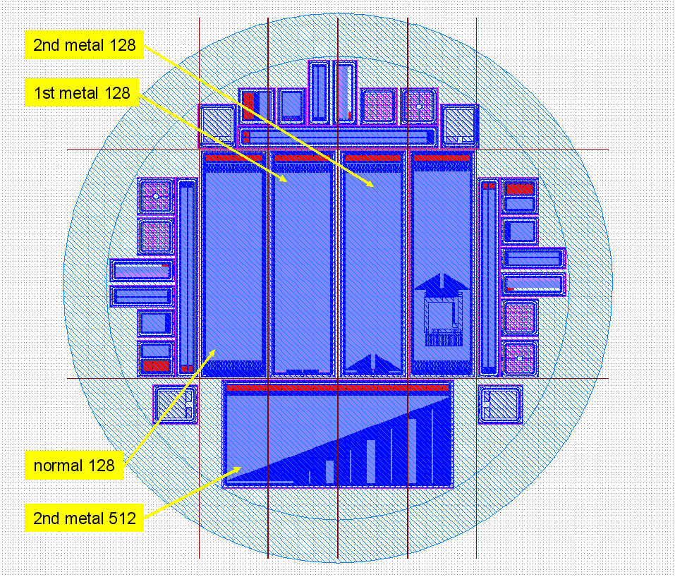
Stephan H�nsel | SiLC | Sensors - layout | | | | |
Pt Modules:
CMS OB1 Sensors:
Optical Modules:
Sensors:
ITE Modules:
|
| Attachment 1: Wafer-Screenshot.png
|
 |
|
7
|
Mon Jul 6 16:22:36 2009 |
Stephan H�nsel | SiLC | Measurements - Sensors | | | | |
Pt Modules:
Optical Modules:
ITE Modules:
|
|
8
|
Mon Jul 6 16:23:51 2009 |
Stephan H�nsel | SiLC | Module Components | | | | |
Pt Modules:
Pt-1:
hybrid: h01-4APV
bottom sensor: 30210331516116
top sensor: 30210332911309
Pt-2:
hybrid: h02-4APV
bottom sensor: 30210331415917
top sensor: 30210314845402
Optical Modules:
Opt_AC-Test-1:
hybrid: h21-2APV
sensor: HPK-ILC-TS-SPL-6687-05
Opt_AC-Test-2:
hybrid: h22-2APV
sensor: HPK-ILC-TS-SPL-6687-07
modules with SiLC alignment sensors:
Opt-1:
hybrid: h03
sensor: HPK-SPL-6686-03
Opt-2:
hybrid: h04
sensor: HPK-SPL-6686-07
ITE Modules: |
|
9
|
Thu Jul 9 10:29:58 2009 |
Stephan H�nsel | SiLC | Measurements - Modules | | | | |
Pt Modules:
- Sensoren sind Luftfeuhtigkeitsempfindlich
- die Sensoren brauchen einige Zeit unter Spannung bis sie sich bei einem akzeptablen Strom stabilisieren
small Problems:
Optical Modules:
small Problems with h03-Module:
ITE Modules:
|
|
17
|
Wed Aug 19 15:41:17 2009 |
Wolfgang Kiesenhofer | SiLC | angle scan templates | | | | |
Linie am rechten Seitenrand (in der Vorschau unten leider nicht gut zu sehen) sollte mit dem rechten Rand der Basisplatte abschließen (bezogen auf die Beam Richtung). |
| Attachment 1: angle_scan0.pdf
|
| Attachment 2: angle_scan5.pdf
|
| Attachment 3: angle_scan10.pdf
|
| Attachment 4: angle_scan15.pdf
|
| Attachment 5: angle_scan20.pdf
|
| Attachment 6: angle_scan25.pdf
|
| Attachment 7: angle_scan30.pdf
|
| Attachment 8: angle_scan35.pdf
|
| Attachment 9: angle_scan40.pdf
|
| Attachment 10: angle_scan45.pdf
|
| Attachment 11: angle_scan50.pdf
|
| Attachment 12: angle_scan55.pdf
|
| Attachment 13: angle_scan60.pdf
|
|
23
|
Thu Aug 20 10:48:39 2009 |
Christian Irmler | alignment_beam | internal calibration | cal002 | | 20.08.2009 10:49:07 | 20.08.2009 10:59:43 |
2 alignement modules
location in beam direction: h04-h03
HV=70V, 40MHz, 1 sample
no beam
module 1 (h03) is used w inverter off and higher base line |
|
24
|
Thu Aug 20 11:05:26 2009 |
Christian Irmler | alignment_beam | pedeatal correction | pedcorr002 | | 20.08.2009 11:05:41 | 20.08.2009 11:09:35 |
2 alignement modules
location in beam direction: h04-h03
HV=70V, 40MHz, 1 sample
beam on
module 1 (h03) is used w inverter off and higher base line |
|
25
|
Thu Aug 20 11:23:04 2009 |
Christian Irmler | alignment_beam | beam in center of sensor w telescope | run004 (6860 telescope) | 10600 | 20.08.2009 11:09:50 | 20.08.2009 11:25:16 |
2 alignement modules
location in beam direction: h04-h03
beam in center of sensor
HV=70V, 40MHz, 6 samples
beam on, 120 GeV
module 1 (h03) is used w inverter off and higher base line
XY coordinates: X:50 y:141.3 (center- center, point 1) |
|
26
|
Thu Aug 20 11:38:11 2009 |
Christian Irmler | alignment_beam | top center, point 7 | run6861 (+6862) | 10600 | 20.08.2009 11:36:35 | 20.08.2009 11:53:51 |
2 alignement modules
location in beam direction: h04-h03
beam in center of sensor
HV=70V, 40MHz, 6 samples
beam on, 120 GeV
module 1 (h03) is used w inverter off and higher base line
XY coordinates: X:50 y:121.3 (top center, point 7) |
|
27
|
Thu Aug 20 12:18:40 2009 |
Christian Irmler | alignment_beam | top left on sensor, point 2 | run6863 (telescope 6864) | 10600 | 20.08.2009 12:07:28 | 20.08.2009 12:25:57 |
2 alignement modules
location in beam direction: h04-h03
beam in center of sensor
HV=70V, 40MHz, 6 samples
beam on, 120 GeV
module 1 (h03) is used w inverter off and higher base line
XY coordinates: X:57 y:121.3 (top left on sensor in beam direction) |
|
28
|
Thu Aug 20 12:35:13 2009 |
Christian Irmler | alignment_beam | top right on sensor, point 3 | run6865 | 10600 | 20.08.2009 12:31:35 | 20.08.2009 12:48:04 |
2 alignement modules
location in beam direction: h04-h03
beam in center of sensor
HV=70V, 40MHz, 6 samples
beam on, 120 GeV
module 1 (h03) is used w inverter off and higher base line
XY coordinates: X:43 y:121.3 (top right on sensor in beam direction) |
|
29
|
Thu Aug 20 12:50:59 2009 |
Christian Irmler | alignment_beam | bottom right on sensor, point 4 | run6866 | 8467 | 20.08.2009 12:51:04 | 20.08.2009 13:05:01 |
2 alignement modules
location in beam direction: h04-h03
beam in center of sensor
HV=70V, 40MHz, 6 samples
beam on, 120 GeV
module 1 (h03) is used w inverter off and higher base line
XY coordinates: X:43 y:155 (bottom right on sensor in beam direction) |
|
30
|
Thu Aug 20 14:31:29 2009 |
Christian Irmler | alignment_beam | bottom left on sensor, point 5 | run6868 | 10600 | 20.08.2009 14:36:00 | 20.08.2009 14:51:57 |
2 alignment modules
location in beam direction: h04-h03
beam in center of sensor
HV=70V, 40MHz, 6 samples
beam on, 120 GeV
module 1 (h03) is used w inverter off and higher base line
XY coordinates: X:57 y:155 (bottom left on sensor in beam direction) |
|
31
|
Thu Aug 20 15:15:33 2009 |
Christian Irmler | alignment_beam | bottom center on sensor, point 6 | run6869 | 615 (beam manipulation by students) | 20.08.2009 14:56:16 | 20.08.2009 15:14:11 |
2 alignment modules
location in beam direction: h04-h03
beam in center of sensor
HV=70V, 40MHz, 6 samples
beam on, 120 GeV
module 1 (h03) is used w inverter off and higher base line
XY coordinates: X:50 y:155 (bottom center on sensor in beam direction) |
|
32
|
Thu Aug 20 15:50:58 2009 |
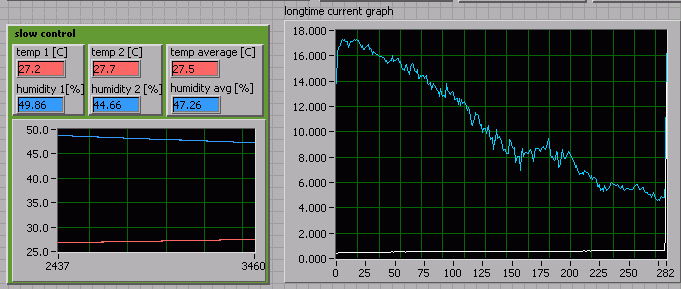
Manfred Valentan | alignment_laser | slow control: HV graph | all alignemnt_laser runs | | 20.08.09 10:36 | 4h 43m 52s later |
blue graph: h03
white graph: h04 |
| Attachment 1: slow_control_alignment_sensors.gif
|
 |
|
34
|
Thu Aug 20 18:56:25 2009 |
Christian Irmler | alignment_laser | laser | laser001 | 100000 | 20.08.2009 18:48:53 | |
2 alignment modules
location in beam direction: h04-h03
laser is shooting on h03 (opposite to the beam)
HV=70V, 40MHz, 6 samples
beam off
module 1 (h03) is used w inverter off
since the signal off the second sensor is only 10 percent, the base line of h03 was increased again (now @ 260 ADC).
5ns trigger pulse width, 1 kHz trigger,
current_laser=10mA,
Photodiode: pulse_width=15ns, amplitude=7mV
bad strips: APV5: 115, APV6: 1 |
|
35
|
Thu Aug 20 19:12:23 2009 |
Manfred Valentan | alignment_laser | background mesurement with laser OFF | laser002 | 10000 | 20.08.2009 19:10:09 | 20.08.2009 19:11:57 |
|
|
36
|
Thu Aug 20 19:15:29 2009 |
Manfred Valentan | alignment_laser | laser on | laser003 | 10000 | 20.08.2009 19:13:04 | 20.08.2009 19:14:49 |
HV=70V, 40MHz, 6 samples, beam off
5ns trigger pulse width, 1 kHz trigger,
current_laser=10mA,
Photodiode: pulse_width=15ns, amplitude=7mV
same settings as run laser001 |
|
37
|
Thu Aug 20 19:35:06 2009 |
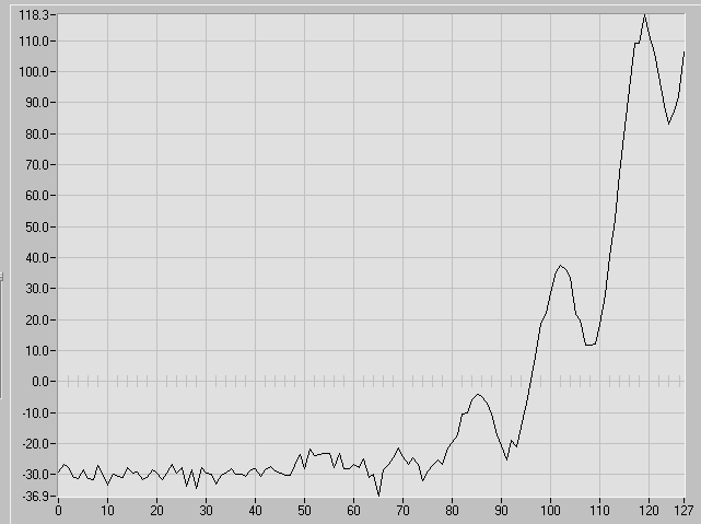
Manfred Valentan | alignment_laser | laser at high intensity (saturation on near sensor, good signal on far sensor) | laser004 | 100000 | 20.08.2009 19:18:47 | 20.08.2009 19:35:05 |
HV=70V, 40MHz, 6 samples, beam off
5ns trigger pulse width, 1 kHz trigger,
current_laser=10mA,
Photodiode: pulse_width=50ns, amplitude=45mV
laser at high intensity (saturation on near sensor, good signal on far sensor)
attached picture shows profile of laser on far sensor creating interferences |
| Attachment 1: laser_interference.png
|
 |