| ID |
Date |
Author |
Project |
Subject |
Run Number |
Events |
StartTime |
EndTime |
|
28
|
Thu Aug 20 12:35:13 2009 |
Christian Irmler | alignment_beam | top right on sensor, point 3 | run6865 | 10600 | 20.08.2009 12:31:35 | 20.08.2009 12:48:04 |
2 alignement modules
location in beam direction: h04-h03
beam in center of sensor
HV=70V, 40MHz, 6 samples
beam on, 120 GeV
module 1 (h03) is used w inverter off and higher base line
XY coordinates: X:43 y:121.3 (top right on sensor in beam direction) |
|
27
|
Thu Aug 20 12:18:40 2009 |
Christian Irmler | alignment_beam | top left on sensor, point 2 | run6863 (telescope 6864) | 10600 | 20.08.2009 12:07:28 | 20.08.2009 12:25:57 |
2 alignement modules
location in beam direction: h04-h03
beam in center of sensor
HV=70V, 40MHz, 6 samples
beam on, 120 GeV
module 1 (h03) is used w inverter off and higher base line
XY coordinates: X:57 y:121.3 (top left on sensor in beam direction) |
|
26
|
Thu Aug 20 11:38:11 2009 |
Christian Irmler | alignment_beam | top center, point 7 | run6861 (+6862) | 10600 | 20.08.2009 11:36:35 | 20.08.2009 11:53:51 |
2 alignement modules
location in beam direction: h04-h03
beam in center of sensor
HV=70V, 40MHz, 6 samples
beam on, 120 GeV
module 1 (h03) is used w inverter off and higher base line
XY coordinates: X:50 y:121.3 (top center, point 7) |
|
25
|
Thu Aug 20 11:23:04 2009 |
Christian Irmler | alignment_beam | beam in center of sensor w telescope | run004 (6860 telescope) | 10600 | 20.08.2009 11:09:50 | 20.08.2009 11:25:16 |
2 alignement modules
location in beam direction: h04-h03
beam in center of sensor
HV=70V, 40MHz, 6 samples
beam on, 120 GeV
module 1 (h03) is used w inverter off and higher base line
XY coordinates: X:50 y:141.3 (center- center, point 1) |
|
24
|
Thu Aug 20 11:05:26 2009 |
Christian Irmler | alignment_beam | pedeatal correction | pedcorr002 | | 20.08.2009 11:05:41 | 20.08.2009 11:09:35 |
2 alignement modules
location in beam direction: h04-h03
HV=70V, 40MHz, 1 sample
beam on
module 1 (h03) is used w inverter off and higher base line |
|
23
|
Thu Aug 20 10:48:39 2009 |
Christian Irmler | alignment_beam | internal calibration | cal002 | | 20.08.2009 10:49:07 | 20.08.2009 10:59:43 |
2 alignement modules
location in beam direction: h04-h03
HV=70V, 40MHz, 1 sample
no beam
module 1 (h03) is used w inverter off and higher base line |
|
22
|
Thu Aug 20 00:31:45 2009 |
Christian Irmler | ITE128 | ITE128 shooting into strips w pitch adapter, upper position | run003 | 100600 | 20.08.2009 00:27:36 | |
DUT: SiLC 08_1, 6 x ITE128, SiLC 08_2
HV = 70V, 40MHz, 120 GeV
TLU trigger, w/o telescope
9x9 mm beam spot
height (y) = 139.3100
ITE128 shooting into strips w pitch adapter, upper edge of sensor |
|
21
|
Thu Aug 20 00:16:45 2009 |
Christian Irmler | ITE128 | pedestal correction | pedcorr001 | | 20.08.2009 00:14:21 | 20.08.2009 00:24:28 |
DUT: SiLC 08_1, 6 x ITE128, SiLC 08_2
HV = 70V, 40MHz
pedestal correction
beam on
|
|
20
|
Wed Aug 19 22:57:13 2009 |
Marko Dragicevic | | How-To | | | | |
TLU (run from DAQPCHEPHY):
ssh eudet@eudetmac001.cern.ch
ssh tlupc
~\eudaq\bin\TLUControl.exe -d1 -a12
-t100 internal trigger
-aXX Mask for Szintis:
1 4 mm (front)
2 4 mm (front)
4 9 mm (back)
8 9 mm (back)
DAQ:
Hostname: DAQPCHEPHY.CERN.CH
XY Table PC:
Hostname: XYPCEUDET.CERN.CH
Beam Control:
Hostname: cwo-hna453-h6b1.cern.ch
137.138.61.206
Eudet DAQ:
vnc eudetmac001.cern.ch
Cycle Run:
o) stop DAQ
o) kill eudaq Run Control
o) restart: ./STARTRUN.FORTIS.1
o) load config: testfortis_with_eudrb_beam_backpressure_WITH_SILC
o) press: Config (wait ~1 min.)
o) press: Start |
|
19
|
Wed Aug 19 22:56:07 2009 |
Christian Irmler | ITE128 | ITE128 shooting into strips w pitch adapter, upper position | run002 | 100600 | 19.08.2009 22:54:23 | 20.08.2009 00:11:31 |
DUT: SiLC 08_1, 6 x ITE128, SiLC 08_2
HV = 70V, 40MHz, 120 GeV
TLU trigger, w/o telescope
9x9 mm beam spot
height (y) = 144.3099
ITE128 shooting into strips w pitch adapter, upper position |
|
18
|
Wed Aug 19 20:43:14 2009 |
Christian Irmler | ITE128 | ITE128 shooting into strips w/o pitch adapter, low position | run001 | 100600 | 19.08.2009 20:42:08 | 19.08.2009 22:54:21 |
DUT: SiLC 08_1, 6 x ITE128, SiLC 08_2
HV = 70V, 40MHz, 120 GeV
TLU trigger, w/o telescope
9x9 mm beam spot
height (y) = 154.0979
ITE128 shooting into strips w/o pitch adapter, low position |
|
17
|
Wed Aug 19 15:41:17 2009 |
Wolfgang Kiesenhofer | SiLC | angle scan templates | | | | |
Linie am rechten Seitenrand (in der Vorschau unten leider nicht gut zu sehen) sollte mit dem rechten Rand der Basisplatte abschließen (bezogen auf die Beam Richtung). |
| Attachment 1: angle_scan0.pdf
|
| Attachment 2: angle_scan5.pdf
|
| Attachment 3: angle_scan10.pdf
|
| Attachment 4: angle_scan15.pdf
|
| Attachment 5: angle_scan20.pdf
|
| Attachment 6: angle_scan25.pdf
|
| Attachment 7: angle_scan30.pdf
|
| Attachment 8: angle_scan35.pdf
|
| Attachment 9: angle_scan40.pdf
|
| Attachment 10: angle_scan45.pdf
|
| Attachment 11: angle_scan50.pdf
|
| Attachment 12: angle_scan55.pdf
|
| Attachment 13: angle_scan60.pdf
|
|
16
|
Wed Aug 19 15:37:37 2009 |
Christian Irmler | ITE128 | internal calibration | cal001 | | 15:31:29 | |
8 modules, HV=70V, 40MHz, 1 sample
no beam
APV 4,5: inverter off, higher baseline = PAD modules |
|
15
|
Fri Aug 14 21:36:17 2009 |
Markus Friedl | | Config files | | | | |
Status of config files as of Friday 14 August 2009 late evening
| Config file name |
Timing adjusted |
Sensor definition |
Tested |
| cern09_ite128_single1 |
YES |
NOT YET (?) |
YES |
|
cern09_ite128_multi6
|
YES |
NOT YET (?) |
YES |
|
cern09_pt_ite512_single1
|
YES |
NOT YET (?) |
YES |
|
cern09_pt_ite512_multi6
|
YES |
NOT YET (?) |
NO |
|
cern09_alignment_beam_single1
|
YES |
NOT YET (?) |
YES |
|
cern09_alignment_beam_multi6
|
YES |
NOT YET (?) |
YES |
|
cern09_belle_single
|
YES |
NOT YET (?) |
YES |
|
cern09_belle_multi6
|
YES |
NOT YET (?) |
YES |
| cern09_silc_all_single |
YES (2008) |
YES (2008) |
NO |
| cern09_silc_all_multi6 |
YES (2008) |
YES (2008) |
NO |
|
|
14
|
Fri Aug 14 19:35:43 2009 |
Thomas Bergauer | Pt_ITE512 | intcal | | | | |
HV=100V except h05-ITE-512 and h06-ITE-512 (runaway, HV off)
h01-Pt: 10uA
h02-Pt: 1.6uA
3 SiLC DUTs mit je ca. 38nA
h07-ITE-512: 3.77uA
h05-ITE-512: breakthrough
h06-ITE-512: breakthrough |
|
13
|
Fri Aug 14 16:45:25 2009 |
Stephan H�nsel | | Module - Setups | | | | |
- 5mm Inbus-Schlüssel
- 3mm Inbus Schlüssel
- 6- 2(1) x 30 Pt-Pins
- beim 5mm-Sockel müssen die 2 Löcher über die das optische Modul h03 verschraubt wird noch ausgeweitet werden (Thomas)
- bei Pt-Deckel oben einzeichnen welche Balkenstellung welchem Winkel entspricht
(SK) ... SenkKopf
(ZK) ... ZylinderKopf
OPTISCHER SETUP - Setup-alignment-modules
upstream - BEAM VON UNTEN - APV-Nummerierung in Beamrichtung von links anfangend
1) Collimator
- Alu-Spacer (neuer = höheren verwenden) + 4- M6 x 15 (ZK)
- schwarzer-Spanier-x-y-z-Tisch - Schreuben dabei -> Plastikschrauben abschneiden ?!?
2) 5mm Spacer + h03 - backplane richtung Collimator - APV3210
- 2- M4 x 15 (SK) - 5mm Spacer durch Alignment-Boden mit h03 verschrauben
- 3- M4 x 15 (SK) - Alignment-Boden auf Drehteller verschrauben
3) h04 - backplane richtung Collimator - APV3210
- 2 Positionen
- 2- M4 x 10 (SK)
Pt + ITE-512-Stack + 3 SiLC08-Module
upstream - BEAM VON UNTEN - APV-Nummerierung in Beamrichtung von links anfangend
1) h06-ITE-512 - APV0123 (allerdings nur eineinhalb APVs gebondet!)
2) h05-ITE-512 - APV0123
3) h07-ITE-512 - APV3210 !!!
4) SiLC08-2 - APV12 - 90° gedreht
5) SiLC08-1 - APV12 - 90° gedreht
6) SiLC08-0 - APV12 - 90° gedreht
Stack 1) bis 6)
- schwarzer Sockel +4- M4 x 35 (ZK) -> verschraubt in h06 und h07
- 2 Gewindestangen M6 x 80 + 4 Scheiben + 4 Muttern M6 -> die 3 ITE-512er zusammen
- 3 Gewindestangen M6 x 160 + 6 Scheiben + 5 Flügelmuttern M6 + 1 Mutter M6 -> 3- SiLC08-Module VORSICHTIG dazu
7) h02-Pt - APV0123 - überprüfen - kann rotieren ;-)
- Schrauben gehen von oben (ausserhalb der Box): Balken - Box-Deckel - Beilagscheibe - Pt-Modul
- Balken + 4- 2(1) x 30 Pins + 2- Scheiben + 2- M4 x 20
8) h01-Pt - APV0123 - überprüfen - kann rotieren;-)
- Schrauben gehen von oben (ausserhalb der Box): Balken - Box-Deckel - Beilagscheibe - Pt-Modul
- Balken + 4- 2(1) x 30 Pins + 2- Scheiben + 2- M4 x 20
ITE128-Stack
upstream - BEAM VON UNTEN - APV-Nummerierung in Beamrichtung von links anfangend
1) h21_alignment-TS05 - APV12 - 90°gedreht
2) h13_ITE-PAS - APV1
3) h14_ITE-PAS - APV1
4) h15_ITE-PAD - APV1
5) h16_ITE-PAD - APV1
6) h11_ITE-STD - APV1
7) h12_ITE-STD - APV1
8) h22-alignment-TS07 - APV12 - 90°gedreht
Schrauben verwenden je nach Sockel und Spacer
SiLC08-Stack
upstream - BEAM VON UNTEN - APV-Nummerierung in Beamrichtung von links anfangend
1) SiLC08-7 - APV12 - Überprüfen
2) SiLC08-6 - APV12 - Überprüfen
3) SiLC08-5 - APV12 - Überprüfen
4) SiLC08-4 - APV12 - Überprüfen
5) SiLC08-3 - APV12 - Überprüfen
6) SiLC08-2 - APV12 - Überprüfen
7) SiLC08-1 - APV12 - Überprüfen
8) SiLC08-0 - APV12 - Überprüfen
Schrauben verwenden je nach Sockel und Spacer |
|
12
|
Tue Aug 11 14:03:57 2009 |
Marko Dragicevic | | Sensor Designs | | | | |
Screenshots
HEPHY Gallery
GDS File Viewer
KLayout Website
Layer Properties File Warsaw.lyp in den Attachments. |
| Attachment 1: Wafer.gds
|
| Attachment 2: SensorSTD.gds
|
| Attachment 3: SensorPAS.gds
|
| Attachment 4: SensorPAD.gds
|
| Attachment 5: Sensor512.gds
|
| Attachment 6: Warsaw.lyp
|
<?xml version="1.0"?>
<layer-properties>
 <properties>
  <frame-color>#01ff6b</frame-color>
  <fill-color>#01ff6b</fill-color>
  <frame-brightness>0</frame-brightness>
  <fill-brightness>0</fill-brightness>
  <dither-pattern>I3</dither-pattern>
  <visible>true</visible>
  <transparent>false</transparent>
  <width>1</width>
  <marked>false</marked>
  <animation>0</animation>
  <name>NPlus</name>
  <source>1/0@1</source>
 </properties>
 <properties>
  <frame-color>#ff0000</frame-color>
  <fill-color>#ff0000</fill-color>
  <frame-brightness>0</frame-brightness>
  <fill-brightness>0</fill-brightness>
  <dither-pattern>I9</dither-pattern>
  <visible>true</visible>
  <transparent>false</transparent>
  <width>1</width>
  <marked>false</marked>
  <animation>0</animation>
  <name>PPlus</name>
  <source>2/0@1</source>
 </properties>
 <properties>
  <frame-color>#ff8000</frame-color>
  <fill-color>#ff8000</fill-color>
  <frame-brightness>0</frame-brightness>
  <fill-brightness>0</fill-brightness>
  <dither-pattern>I0</dither-pattern>
  <visible>true</visible>
  <transparent>false</transparent>
  <width>1</width>
  <marked>false</marked>
  <animation>0</animation>
  <name>Via</name>
  <source>3/0@1</source>
 </properties>
 <properties>
  <frame-color>#00ffff</frame-color>
  <fill-color>#00ffff</fill-color>
  <frame-brightness>0</frame-brightness>
  <fill-brightness>0</fill-brightness>
  <dither-pattern>I15</dither-pattern>
  <visible>true</visible>
  <transparent>false</transparent>
  <width>1</width>
  <marked>false</marked>
  <animation>0</animation>
  <name>Metal</name>
  <source>4/0@1</source>
 </properties>
 <properties>
  <frame-color>#ff00ff</frame-color>
  <fill-color>#ff00ff</fill-color>
  <frame-brightness>0</frame-brightness>
  <fill-brightness>0</fill-brightness>
  <dither-pattern>I2</dither-pattern>
  <visible>true</visible>
  <transparent>false</transparent>
  <width>1</width>
  <marked>false</marked>
  <animation>0</animation>
  <name>Passivation</name>
  <source>5/0@1</source>
 </properties>
 <properties>
  <frame-color>#91ff00</frame-color>
  <fill-color>#91ff00</fill-color>
  <frame-brightness>0</frame-brightness>
  <fill-brightness>0</fill-brightness>
  <dither-pattern>I3</dither-pattern>
  <visible>true</visible>
  <transparent>false</transparent>
  <width>1</width>
  <marked>false</marked>
  <animation>0</animation>
  <name>PolySilicon</name>
  <source>6/0@1</source>
 </properties>
 <properties>
  <frame-color>#008050</frame-color>
  <fill-color>#008050</fill-color>
  <frame-brightness>0</frame-brightness>
  <fill-brightness>0</fill-brightness>
  <dither-pattern>I2</dither-pattern>
  <visible>true</visible>
  <transparent>false</transparent>
  <width>1</width>
  <marked>false</marked>
  <animation>0</animation>
  <name>PolySiHeads</name>
  <source>7/0@1</source>
 </properties>
 <properties>
  <frame-color>#ffa080</frame-color>
  <fill-color>#ffa080</fill-color>
  <frame-brightness>0</frame-brightness>
  <fill-brightness>0</fill-brightness>
  <dither-pattern>I0</dither-pattern>
  <visible>true</visible>
  <transparent>false</transparent>
  <width>1</width>
  <marked>false</marked>
  <animation>0</animation>
  <name>Via2</name>
  <source>8/0@1</source>
 </properties>
 <properties>
  <frame-color>#000080</frame-color>
  <fill-color>#000080</fill-color>
  <frame-brightness>0</frame-brightness>
  <fill-brightness>0</fill-brightness>
  <dither-pattern>I12</dither-pattern>
  <visible>true</visible>
  <transparent>false</transparent>
  <width>1</width>
  <marked>false</marked>
  <animation>0</animation>
  <name>Metal2</name>
  <source>10/0@1</source>
 </properties>
 <properties>
  <frame-color>#ffa080</frame-color>
  <fill-color>#ffa080</fill-color>
  <frame-brightness>0</frame-brightness>
  <fill-brightness>0</fill-brightness>
  <dither-pattern>I1</dither-pattern>
  <visible>true</visible>
  <transparent>false</transparent>
  <width>1</width>
  <marked>false</marked>
  <animation>0</animation>
  <name>Margins</name>
  <source>11/0@1</source>
 </properties>
 <properties>
  <frame-color>#805000</frame-color>
  <fill-color>#805000</fill-color>
  <frame-brightness>0</frame-brightness>
  <fill-brightness>0</fill-brightness>
  <dither-pattern>I0</dither-pattern>
  <visible>true</visible>
  <transparent>false</transparent>
  <width>1</width>
  <marked>false</marked>
  <animation>0</animation>
  <name>Dicing Lines</name>
  <source>12/0@1</source>
 </properties>
 <custom-dither-pattern>
  <pattern>
   <line>................................</line>
   <line>................................</line>
   <line>................................</line>
   <line>................................</line>
   <line>................................</line>
   <line>................................</line>
   <line>................................</line>
   <line>................................</line>
   <line>................................</line>
   <line>................................</line>
   <line>................................</line>
   <line>................................</line>
   <line>................................</line>
   <line>................................</line>
   <line>................................</line>
   <line>................................</line>
   <line>................................</line>
   <line>................................</line>
   <line>................................</line>
   <line>................................</line>
   <line>................................</line>
   <line>................................</line>
   <line>................................</line>
   <line>................................</line>
   <line>................................</line>
   <line>................................</line>
   <line>................................</line>
   <line>................................</line>
   <line>................................</line>
   <line>................................</line>
   <line>................................</line>
   <line>................................</line>
  </pattern>
  <order>1</order>
  <name></name>
 </custom-dither-pattern>
</layer-properties>
|
|
11
|
Fri Jul 31 19:23:26 2009 |
Thomas Bergauer | | Laser Spot size | | | | |
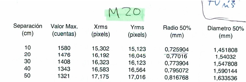
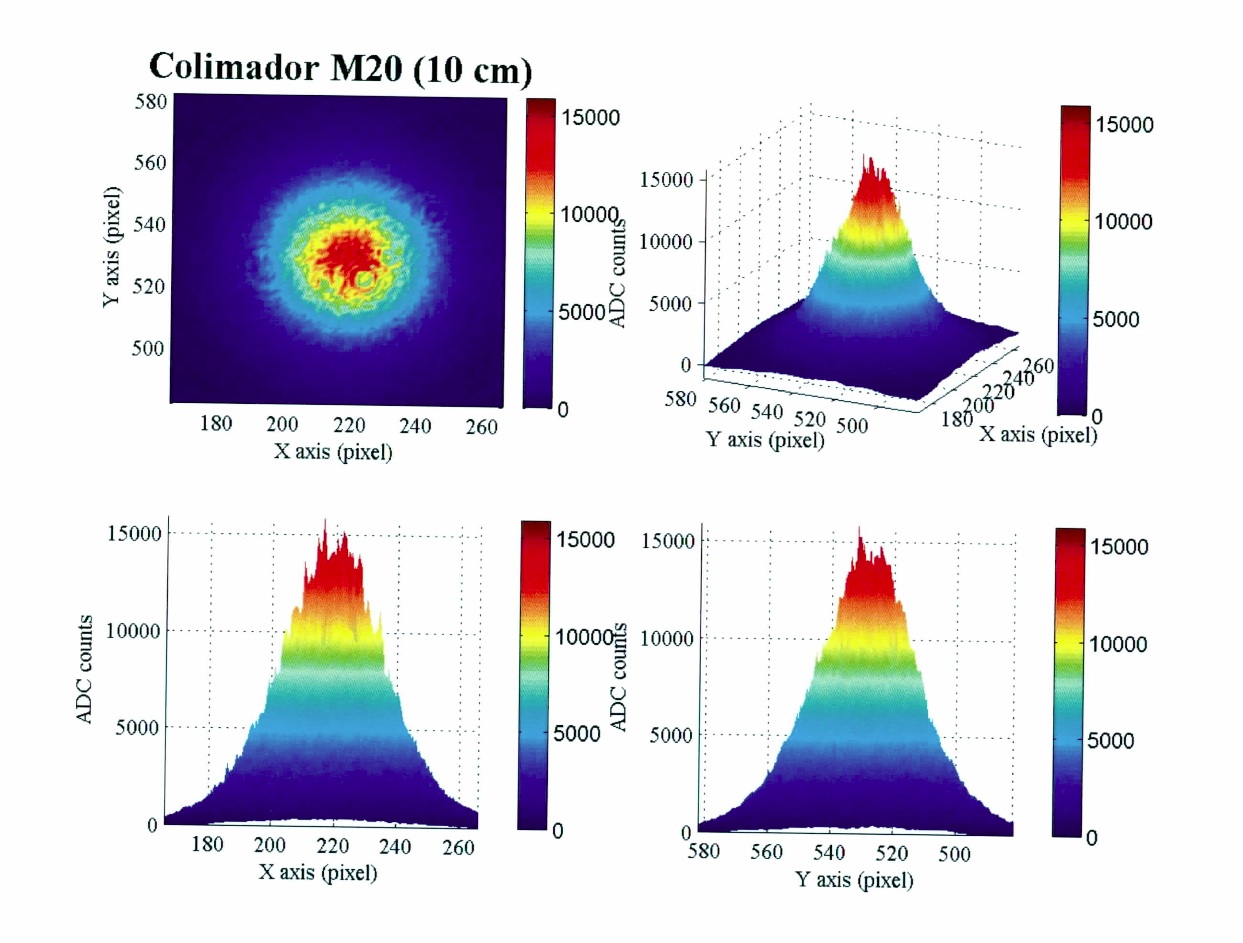
| 10cm nach Kollimator: Durchmesser 1.45mm (FWHM)
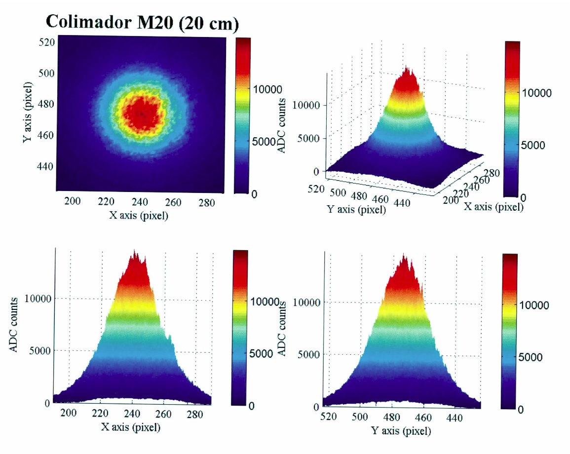
20cm nach Kollimator: Durchmesser 1,54mm (FWHM) |
| Attachment 1: laser_spot_overview.jpg
|
 |
| Attachment 2: laser_spot_10cm.jpg
|
 |
| Attachment 3: laser_spot_20cm.jpg
|
 |
| Attachment 4: laser_spot_30cm.jpg
|
 |
|
10
|
Fri Jul 17 14:03:21 2009 |
Stephan H�nsel | | What to measure | | | | |
Origami
Testbeam08 Module
- Anglescan
Pt Modules (2Stück - je 2 Sensoren):
Anglescan
- einzelne module (auch als "stub" (fixer Abstand zwischen ihnen) ?)
wichtig: brauchen wir 2 Testbeam08 module um 90° verdreht für höheninformation??? (sensoren in den Pt-modulen sind nicht 100%ig parallel - MESSEN!)
Optical Modules:(DAUER ca 18 Stunden)
- tests in box mit laserbeam (laser auf anderer Höhe al beam?!? - sonst geht der beam durch den Laser)
ITE Modules:
- 8 ter stack: (2 Testbeam08 module quer + 2 x 1stmetal128 + 2 x 2nd metal 128 + 2 x normal128)
- 2ndmetal512 module 3 stück bauen und im beam versetzt einbauen parasitär bei den spanier-modulen)
zusätliche ideen:
- CMS-Tracker slice (2Pt + 2 optische + 3 2ndmetal512 hintereinander in unterschiedlichen winkeln um einen tracker-slice zu simulieren - CMS-layout !?!)
|
|
9
|
Thu Jul 9 10:29:58 2009 |
Stephan H�nsel | SiLC | Measurements - Modules | | | | |
Pt Modules:
- Sensoren sind Luftfeuhtigkeitsempfindlich
- die Sensoren brauchen einige Zeit unter Spannung bis sie sich bei einem akzeptablen Strom stabilisieren
small Problems:
Optical Modules:
small Problems with h03-Module:
ITE Modules:
|