| ID |
Date |
Author |
Project |
Subject |
Run Number |
Events |
StartTime |
EndTime |
Data |
|
48
|
Sat Oct 8 00:14:37 2011 |
Christian Irmler | BELLE | Origami stack | run015 | 180111 | 08.10.2011 00:06:41 | 08.10.2011 08:24:38 | Good |
Origami6
HV=+-40V,
no cooling
beam on; xy table position x=306 y=74.5
Istart=57µA;
std. I2C settings
centered
currents:
8.10.2011 00:07:43 event=991 rate=0events/s temp/curr=33.0/-15.4 33.0/-17.3 33.0/-17.7 31.9/011.5 31.9/013.2 32.0/040.20
...
08.10.2011 06:32:34 event=179710 rate=0events/s temp/curr=33.1/-22.1 33.0/-25.6 33.1/-22.6 31.9/018.2 31.8/021.7 31.9/048.5
08.10.2011 06:33:28 event=180105 ***WARNING*** Error detected in APV 0, subevent 2. Event discarded, reset sent.
Permanent APV errors at several (all p-side, some n-side) APV chips after 180105 events, which could not be recovered by software resets. After restart of run, all APVs where alive again, hence hardware reset and I2C reconfiguration after 5 or 10 consecutive APV errors should be added to TUXDAQ software.
After APV errors occured, the cummulative bias current decrised from 78µA to 54µA. This effect can occures whenever the digital part of the APV is switched between idle and full operation. It seems that this is a thermal effect, caused by the slightly higher power consumption of the digital part of the chips.
|
|
49
|
Sat Oct 8 09:30:44 2011 |
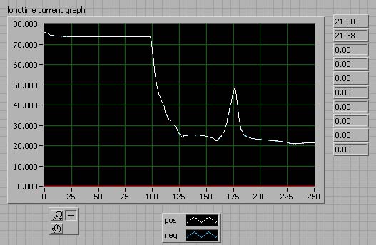
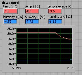
Christian Irmler | BELLE | Cooling plant tests | | | 08.10.2011 09:30 | | Unknown |
Software run with 6 samples to ensure that APV chips dissipate full power.
DAQ data not saved, bias current monitored
new longterm files:
It-neg-0810110926.txt
It-pos-0810110926.txt |
| Attachment 1: biascurrent_cooling_test1.jpg
|
 |
| Attachment 2: temp_cooling_test1.jpg
|
 |
|
50
|
Sat Oct 8 14:33:25 2011 |
Thomas Bergauer | HPK | baby_std | run016 | 250k | 08.10.2011 14:31:40 | | Crap |
falsches config file (single statt multi6)
no cooling
beam on; xy table position x=322 y=80
HV=200V Istart_PY=7.6uA; Istart_N=0.42
std. I2C settings |
|
51
|
Sat Oct 8 16:35:04 2011 |
Thomas Bergauer | HPK | baby_std | run017 | | 08.10.2011 16:26:10 | | Crap |
wrong timing
no cooling
beam on; xy table position x=322 y=80
HV=200V Istart_PY=7.6uA; Istart_N=0.42
std. I2C settings |
|
52
|
Sat Oct 8 16:45:14 2011 |
Thomas Bergauer | HPK | baby_std | run018 | 150000 | 08.10.2011 16:44:13 | 08.10.2011 19:33:33 | Good |
no cooling
beam on; xy table position x=322 y=80
HV=200V Istart_PY=8.2uA; Istart_N=0.45uA
std. I2C settings, now with correct timing |
|
53
|
Sat Oct 8 20:33:58 2011 |
Karl-Heinz Hoffmann | HPK | baby_std | run019 | 150000 | 08.10.2011 20:22:45 | 08.10.2011 23:19:23 | Good |
no cooling
beam on; xy table position x=333 y=80
HV=200V Istart_PY=8.2uA; Istart_N=0.45uA
std. I2C settings |
|
54
|
Sat Oct 8 23:27:44 2011 |
Karl-Heinz Hoffmann | HPK | baby_std | run020 | 382000 | 08.10.2011 23:24:16 | 09.10.2011 09:24:20 | Good |
no cooling
beam on; xy table position x=327,5 y=65
HV=200V Istart_PY=8.2uA; Istart_N=0.45uA
std. I2C settings |
|
55
|
Sun Oct 9 10:05:34 2011 |
Markus Friedl | HPK | baby_std | cal010 | 83800 | 08.10.2011 13:36:25 | 08.10.2011 13:54:07 | Good |
HV=+-40V,
no cooling
beam off; xy table position x= y=
HV= Istart=uA;
std. I2C settings
|
|
56
|
Sun Oct 9 10:13:11 2011 |
Karl-Heinz Hoffmann | HPK | baby_add | cal011 | 83800 | 09.10.2011 10:05:01 | | Good |
no cooling
beam on; xy table position x= y=
HV=200V Istart_P=1.5uA; Istart_N=0.22uA
std. I2C settings |
|
57
|
Sun Oct 9 11:00:33 2011 |
Karl-Heinz Hoffmann | HPK | baby_add | run021 | 150000 | 09.10.2011 10:56:47 | 09.10.2011 12:47:23 | Good |
no cooling
beam on; xy table position x=330 y=74
HV=200V Istart_PY=1,9uA; Istart_N=0.27uA
std. I2C settings |
|
58
|
Sun Oct 9 11:28:30 2011 |
Manfred Valentan | HPK | HPK BSTD stack configuration | | | | | Unknown |
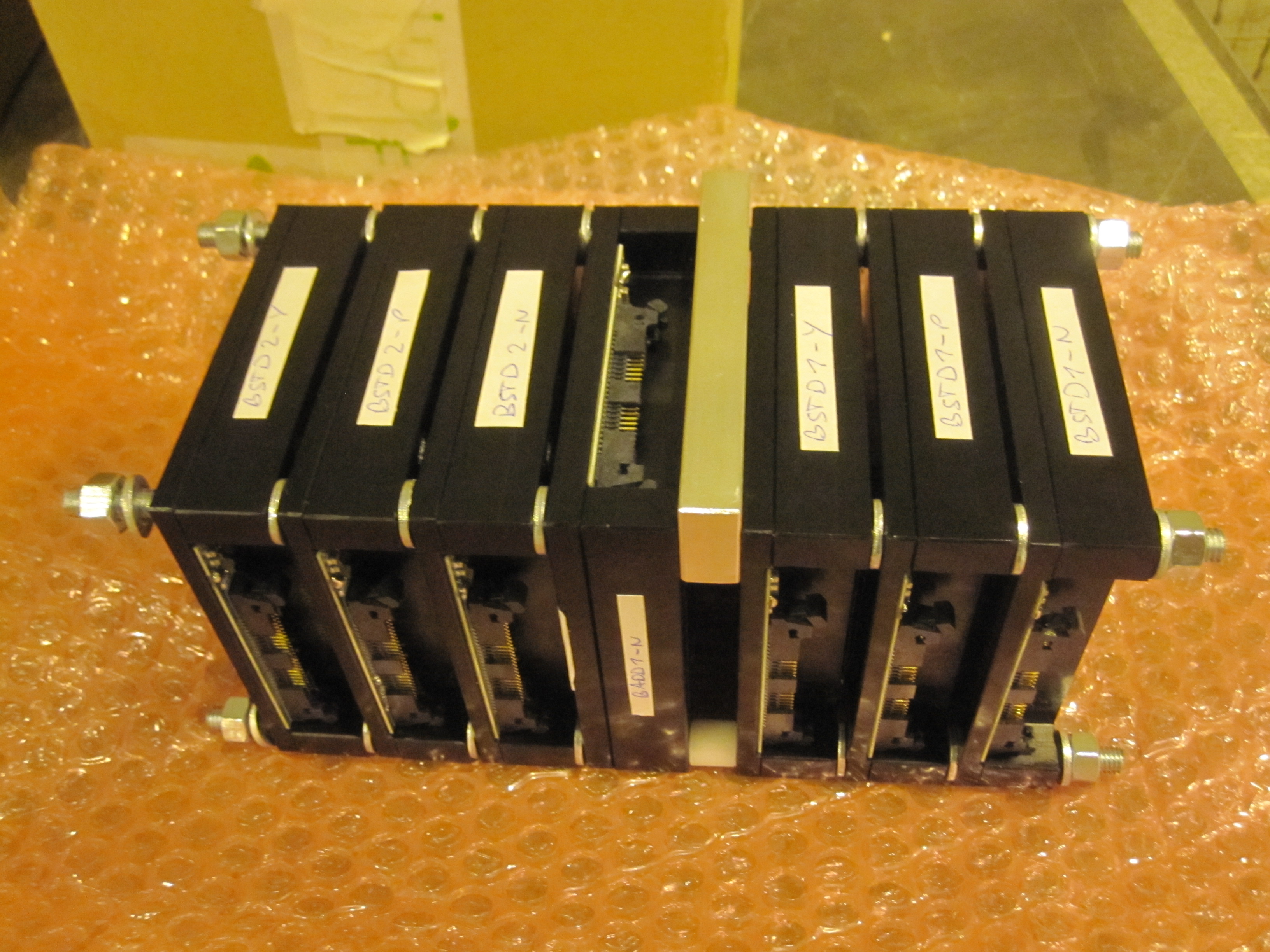
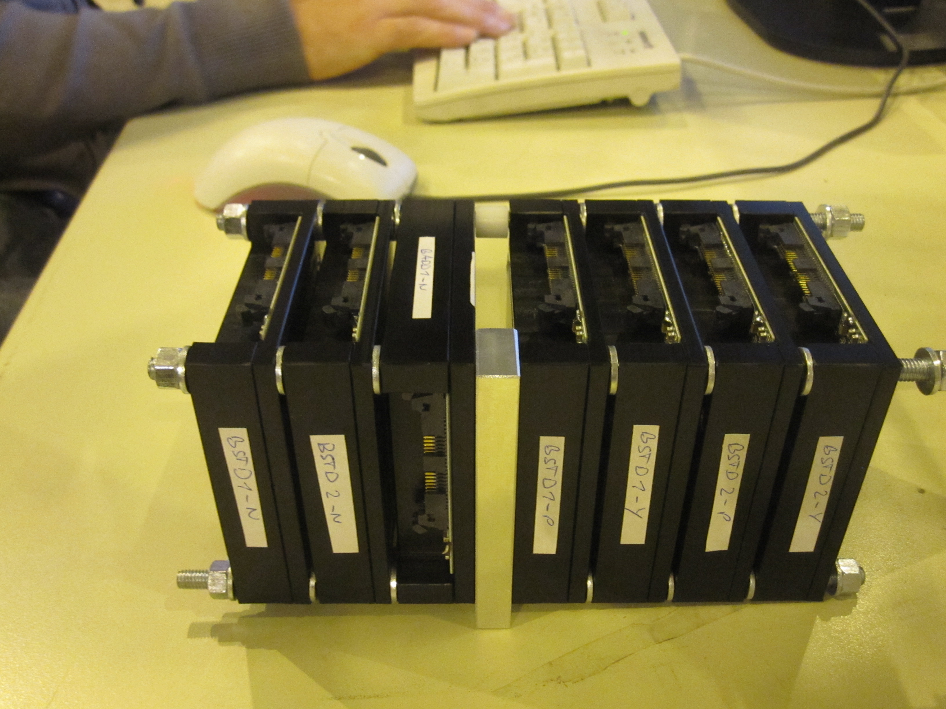
Module order:
BSTD1-N
BSTD2-N
BADD1-N (for z information)
BSTD1-P
BSTD1-Y
BSTD2-P
BSTD2-Y
Talk from Marko on Testbeam with HPK Double Metal Sensors |
| Attachment 1: IMG_5058.JPG
|
 |
| Attachment 2: IMG_5069.JPG
|
 |
|
59
|
Sun Oct 9 11:31:43 2011 |
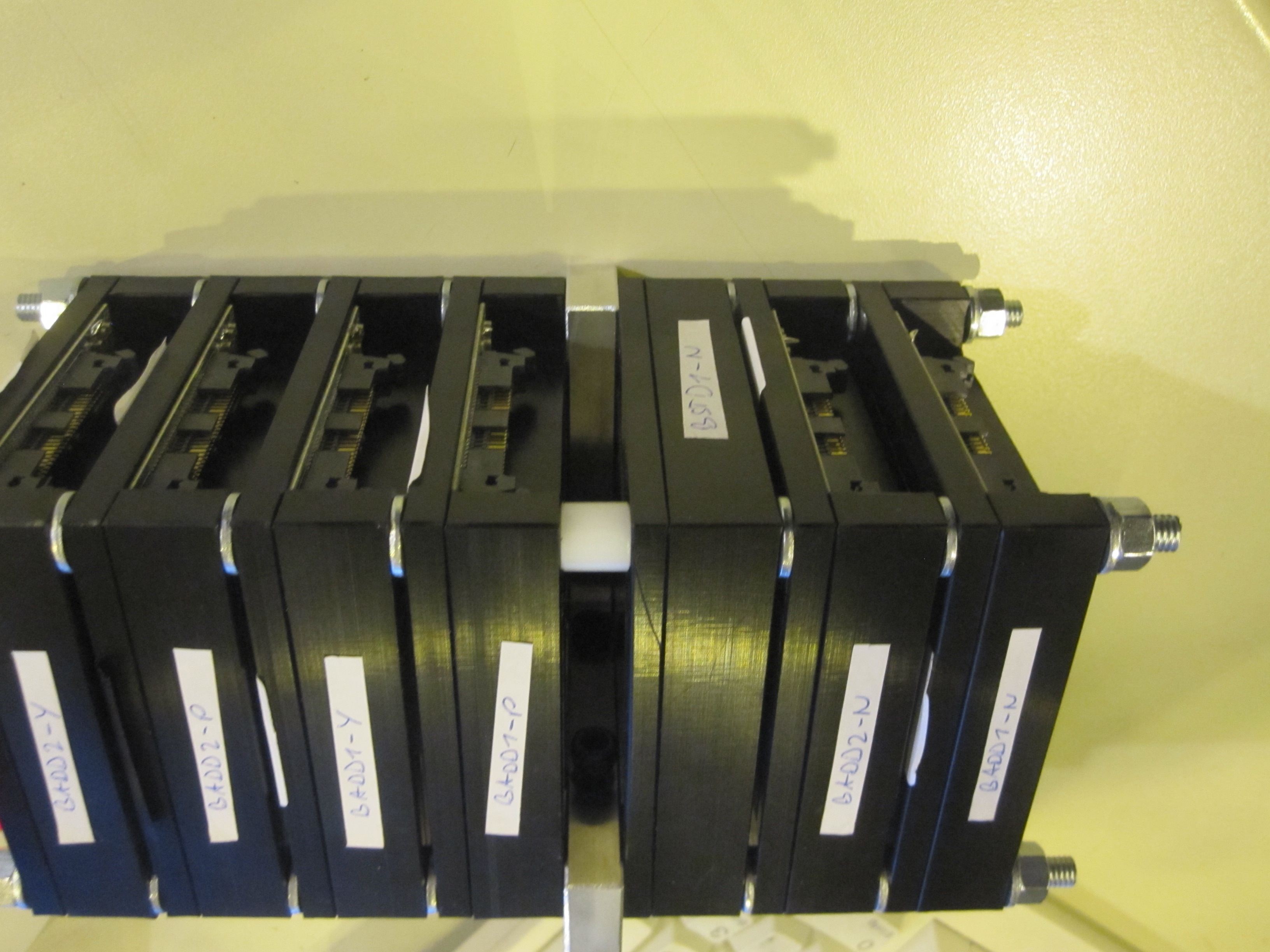
Manfred Valentan | HPK | HPK BADD stack configuration | | | | | Unknown |
Module order:
BADD1-N
BADD2-N
BSTD1-N (for z information)
BADD1-P
BADD1-Y
BADD2-P
BADD2-Y
Talk from Marko on Testbeam with HPK Double Metal Sensors |
| Attachment 1: IMG_5097.JPG
|
 |
|
60
|
Sun Oct 9 13:12:32 2011 |
Karl-Heinz Hoffmann | HPK | baby_add | run022 | 670k | 09.10.2011 13:09:32 | 10.10.2011 00:48:16 | Good |
no cooling
beam on; xy table position x=330 y=64
HV=200V Istart_PY=1,9uA; Istart_N=0.27uA
std. I2C settings |
|
61
|
Mon Oct 10 00:50:23 2011 |
Christian Irmler | HPK | baby_add | run023 | 680k | 10.10.2011 00:51:26 | 10.10.2011 09:15:35 | Good |
no cooling
beam on; xy table position x=330 y=74
HV=200V Istart_PY=1,9uA; Istart_N=0.27uA
std. I2C settings
same as run021, but taking more events |
|
62
|
Mon Oct 10 10:37:52 2011 |
Christian Irmler | CNM | CNM stack | cal012 | 83800 | 10.10.2011 11:29:55 | 10.10.2011 11:40:55 | Unknown |
no cooling
beam on; xy table position x=330 y=64
HV_CNM=20V, HV_BSTD1=200V
Istart_CNM= 28 / 1 uA; Istart_BSTD= 0.12 uA |
|
63
|
Mon Oct 10 12:15:52 2011 |
Manfred Valentan | CNM | CNM stack | run024 | 110000 | 10.10.2011 12:03:58 | 10.10.2011 14:05:56 | Good |
no cooling
beam on; xy table position x=320.5 y=79.5
HV_CNM=20V, HV_BSTD1-N=200V
Istart_CNM= 28 / 1 uA; Istart_BSTD= 0.12 uA |
|
64
|
Mon Oct 10 12:16:06 2011 |
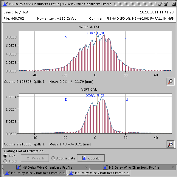
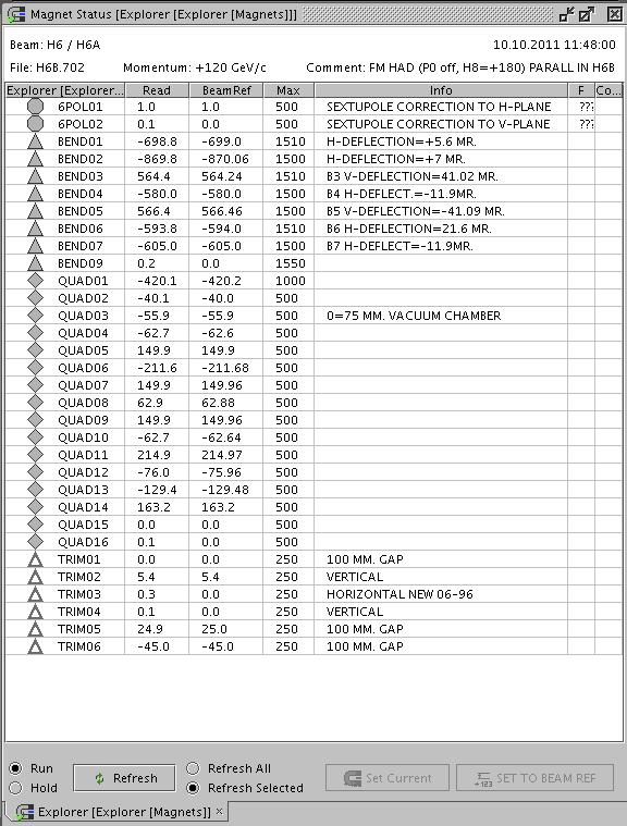
Marko Dragicevic | common | Beam Profile and Magnet BeamRef Settings | | | | | Unknown |
Beam Profile from H6A, 10.10.2011 11:40
BeamRef settings for all magnets, File H6B.702 |
| Attachment 1: BeamProfile.png
|
 |
| Attachment 2: MagentBeamRefs.png
|
 |
|
65
|
Mon Oct 10 12:32:42 2011 |
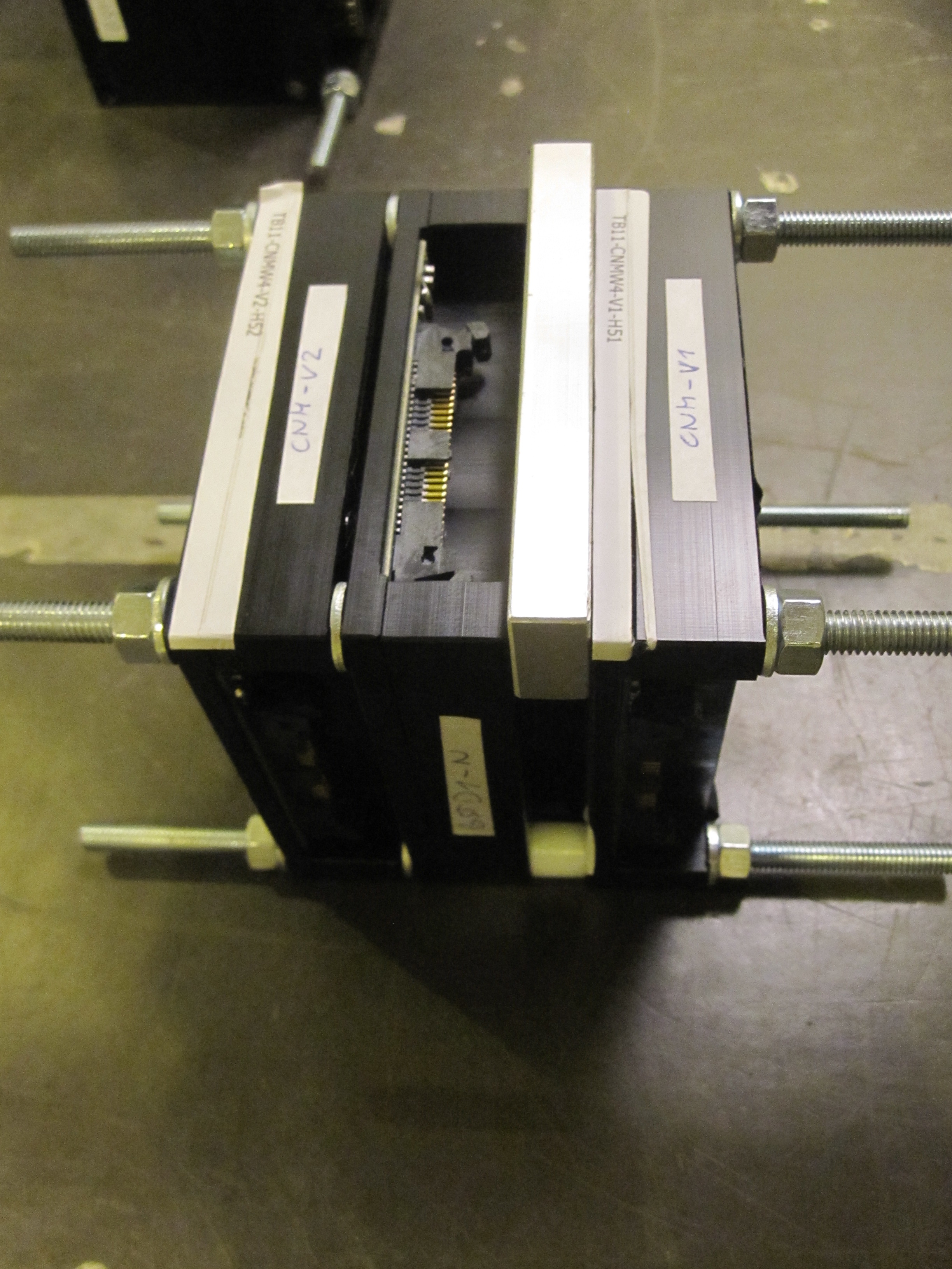
Manfred Valentan | CNM | CNM stack configuration | | | | | Unknown |
Module order:
CNM-V1 (draws a lot of current, gives only low signal)
BSTD1-N (for height information)
CNM-V2 (works fine)
Attatchment 1: Stack config, beam from right. In the box the stack is mounted with the labelled side of the BSTD1-N module on top (90deg rotated w.r.t. photo)
Attachment 2: the top edges of the sensors coincide -> when the beam hits the last strips of the BSTD, it also hits the pitch adapter region of the CNM sensors |
| Attachment 1: IMG_5102.JPG
|
 |
| Attachment 2: IMG_5092.JPG
|
 |
|
66
|
Mon Oct 10 14:11:53 2011 |
Christian Irmler | CNM | CNM stack | run025 | 110000 | 10.10.2011 14:09:00 | 10.10.2011 16:11:57 | Good |
no cooling
beam on; xy table position x=335.5 y=79.5
HV_CNM=20V, HV_BSTD1-N=200V
Istart_CNM= 31 / 1.4 uA; Istart_BSTD= 0.2 uA |
|
67
|
Mon Oct 10 16:26:20 2011 |
Marko Dragicevic | CNM | CNM stack | run026 | 300000 | 10.10.2011 16:23:46 | 10.10.2011 20:30:00 | Good |
no cooling
beam on; xy table position x=328 y=69.5
HV_CNM=20V, HV_BSTD1-N=200V
Istart_CNM= 27 / 1.5 uA; Istart_BSTD= 0.2 uA |